
Keeping LNG Carriers Safe: The Importance of Pipe Stress Analysis
At GTT, ensuring the integrity of cryogenic pipe networks is a core part of our contribution to LNG carrier design. These systems, which carry LNG at extremely low temperatures, present unique engineering challenges. Among them, pipe stress analysis is essential - not only because it is required by the IGC Code, but also because it helps prevent leaks, ruptures, and other failures that could affect the vessel, its crew, the environment, and the cargo.
Several factors contribute to the complexity of stress analysis for cryogenic pipe, making it significantly more demanding than for networks operating at room temperature:
1. Extreme Temperature Variations: Cryogenic fluids such as Liquid Nitrogen (-196°C) and LNG (-165°C) cause large temperature differences compared with ambient conditions. This leads to significant thermal contraction of the pipe and, if not properly pre-cooled, bowing effects as the pipe bends under uneven temperatures.
Rapid cool-down and warm-up cycles can induce thermal shock, creating high stresses that may cause cracking, deformation of pipe anchorages and supports, or loss of tightness in joints and flanges.
Because these variations are far greater than conventional systems, stress analysis is essential to ensure materials and supports can withstand safely.
2. Complex Loading Conditions
Cryogenic pipesystems on an LNG Carrier are subject to various loading conditions:
Weight Loads: The weight due to permanent loads (pipe, insulation, fluid, …) and the weight due to temporary loads (snow, ice, ...) have to be considered during the pipe stress analysis.
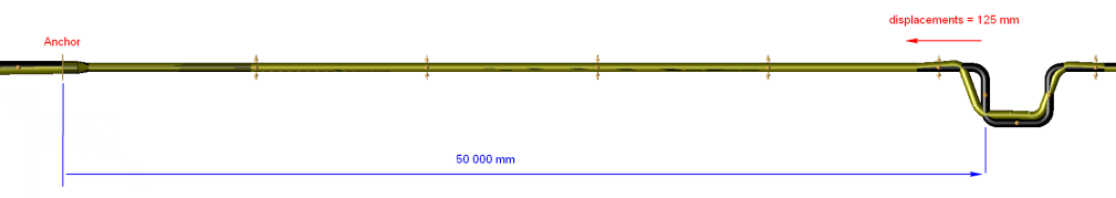
Thermal Loads: As described above, thermal expansion and contraction are major contributors to stress during operation. For instance, the thermal shrinkage of a Stainless Steel line operating at -165°C is around 2.5 mm/m, which means that a straight pipe of 50 meters - anchored at one side - will shrink about 125 mm.
In addition, the pipe stress analyst must consider all operating modes and ensure that all of them will be ASME B31.3 code compliant.
- Pressure Loads: The internal pressure of the cryogenic fluid exerts hoop stress on the pipe thickness that must be considered in conjunction with other loads. The pressure will have an important impact on the lines where Axial Expansion Joints are provided; the generated pressure thrust will have to be handled by supporting structures. For example, the pressure thrust to be withstood by the adjacent structure of an Axial Expansion Bellow installed on a 24” diameter pipe (wall thickness 6.35 mm) with a pressure of 10 bar will be around 280 kN (= 28 tons, to be compared with the weight of a pump tower which is around 40 tons).
- Inertial Acceleration: LNG Carriers are subject to accelerations due to waves and sea conditions. For example, applying an acceleration equal to 0.3g leads to an increase in the pipe weight and all connected items by 30% and generate additional horizontal loads on pipe supports equal to 30% of the pipe weight.
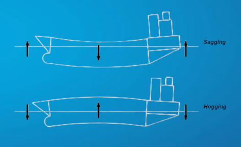
- Hull Deformation: The hull of an LNG Carrier can deform under various loading conditions, such as cargo weight (depending on tank and ballast levels) and wave action Acting like a beam, the vessel bends and imposes displacements on pipe supports. Two main types are considered: hogging (bending upward at midship) and sagging (bending downward at midship). Combined with thermal effects, these deformations increase stresses in the pipes as well as the reaction forces on supports and equipment.
- Dynamic Loads: These are loads that will fluctuate rapidly over time, such as Pressure Relief Valve opening, Slug Flow and Water Hammer. Slug flow is a phenomenon that occurs under special circumstances of two-phase gas-liquid flow and is the most serious scenario in a two-phase flow as it involves a moving liquid mass pushed by gases in between. Water Hammer refers to rapid and often large pressure and flow fluctuations resulting from transient flow conditions (ex: gradual or sudden valve closure, pump trip, etc.). These events generate reaction forces at any change in flow direction (elbows, tee, etc.)
- Connection Loads at the manifolds as per SIGTTO (Society of International Gas Tanker and Terminal Operators) recommendations shall be considered during the analysis to ensure the design of the manifold supports. Those loads, applied on the manifold, are applied during cargo transfer when Marine Loading Arms are connected to the ship manifold.
-
Vibration Loads: Pipe lines are subject to vibrations on an LNG Carrier. The two most likely sources of excitation are the engine and the propeller.
3. Support & Restraint Loads: The pipe support configuration (location & function) will significantly influence the stress distribution in the system. The pipe stress analyst must select and model these supports accurately to ensure the correct behaviour of the lines by checking that the pipe system will be able to withstand any expected loads without excessive stress.
4. Safety & Environmental Concerns: The consequences of a leak or rupture in a cryogenic cargo line can be severe. Release of cryogenic fluids can lead to frostbite and cryogenic burns, material embrittlement, and environmental damage.
How Pipe Stress Analysis Mitigates Risks
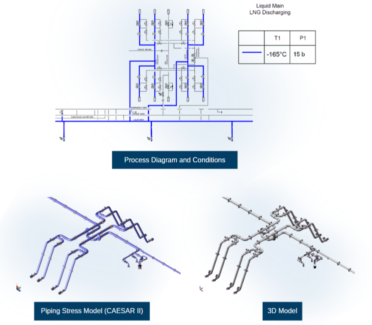
By using different inputs as the Process Diagram, Process conditions and 3D models, the pipe stress analysis will play a crucial role in mitigating these risks.
Identifying High-Stress Areas: The pipe stress analyst will highlight locations where stresses exceed allowable limits (for example elbows from pipe expansion loop, small branch connections, etc.) and proposes modifications in conjunction with the pipe designer.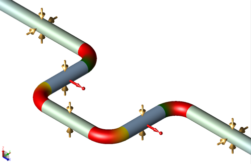
Optimising Support Configuration: The analyst will define the pipe support configuration (location and functions) based on the pipe layout in order to minimise stress concentrations and control thermal expansion.
Selecting Appropriate Materials: The analyst will recommend the selection of fittings that will have sufficient strength to withstand stresses.
Designing Expansion Joints & Pipe Loops: The pipe stress analyst will define expansion loops sizes and locations and define expansion joint characteristics to absorb thermal expansion and prevent excessive stresses.
Validating Design Adequacy: The analyst will ensure that the pipe system meets all applicable codes and standards requirements and check:
- The calculated stresses within code allowable levels (example: ASME B31.3),
- The loads on pipe supports as per recommended values,
- The loads on equipment nozzles as per Vendor requirements or recognised standards (example NEMA SM23, API 610, etc.),
- The displacements of the lines as per recommended values (example: limited pipe deflection in sustained case, etc.),
- The first natural frequencies of the pipe arrangement as per recommended values – the limitation of pipe displacements as described above will allow to provide stiffer network and therefore increase the first natural frequency.
Pipe stress analysis translates complex operating conditions into practical design rules, ensuring that cargo lines remain safe, reliable, and compliant. It is an essential step in delivering robust LNG carrier systems.
By overseeing stress analysis for the most critical pipe networks on membrane LNG carriers, GTT brings essential expertise that contributes directly to the safe and reliable design of these vessels.